Tunnels
Tunnels share a similar property to recursive routes in that after applying the tunnel encapsulation, a new packet must be forwarded, i.e. forwarding is recursive. However, as with recursive routes the tunnel’s destination is known beforehand, so the recursive switch can be avoided if the packet can follow the already constructed data-plane graph for the tunnel’s destination. This process of joining to DP graphs together is termed stacking.
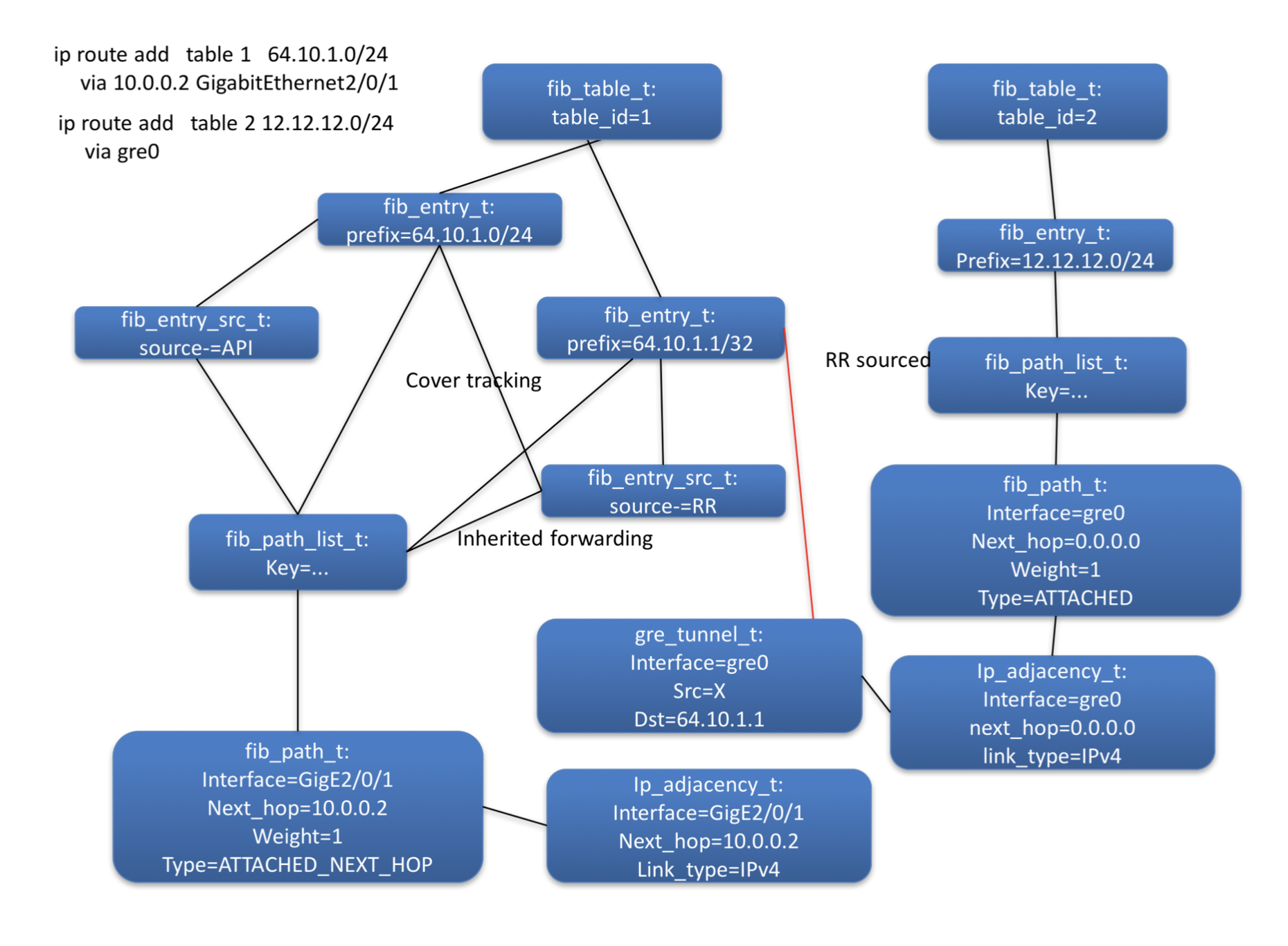
Figure 11: Tunnel control plane object diagram
Figure 11 shows the control plane object graph for a route via a tunnel. The two sub-graphs for the route via the tunnel and the route for the tunnel’s destination are shown to the right and left respectively. The red line shows the relationship form by stacking the two sub-graphs. The adjacency on the tunnel interface is termed a ‘mid-chain’ this it is now present in the middle of the graph/chain rather than its usual terminal location.
The mid-chain adjacency is contributed by the gre_tunnel_t , which also becomes part of the FIB control-plane graph. Consequently it will be visited by a back-walk when the forwarding information for the tunnel’s destination changes. This will trigger it to restack the mid-chain adjacency on the new load_balance_t contributed by the parent fib_entry_t.
If the back-walk indicates that there is no route to the tunnel, or that the route does not meet resolution constraints, then the tunnel can be marked as down, and fast convergence can be triggered in the same way as for physical interfaces (see section …).